Introduction to LogicLab – Basic demo
Basic demo application
This is a simple demo to show some basic features of LogicLab, related to IEC standard; it contains: examples coding for all 5 languages of the standard, declaration and usage of functions and function blocks, arrays and mapped variables…
The following instructions show how to download and execute the demo application, give a general description of its content, and make some exampe on how to use some of the debug instruments.
You can download the basic demo application project at the following link: LLExec_Basic_Demo.
We recommend you to get acquired with the environment, reading page “Getting started” before trying out the demo.
Install, open project and download
- Download the demo application and extract it to the desired location
- Follow instructions indicated in page “Getting started”, at the “Install procedure” paragraph, to install LogicLab and LLExec for Ubuntu x64.
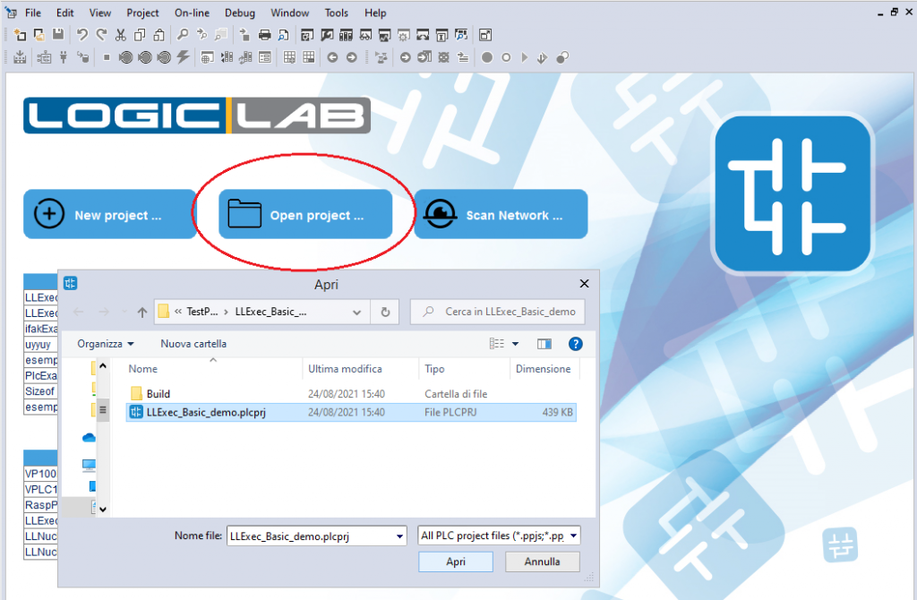
- Now launch LogicLab but, instead of creating a new project, choose to open an already existing project and select the LLExec_Basic_demo.plcprj.
- For connecting to the target, please, follow instructions indicated in page “Getting started”, at the “Connecting to the target” paragraph
- For compiling and downloading the application, follow instructions indicated in page “Getting started”, at the “Compile, download and verify” paragraph
- Now the output status, in the bottom-right border, should display SOURCE OK and CONNECTED
FBD (Function Block Diagram) editor example
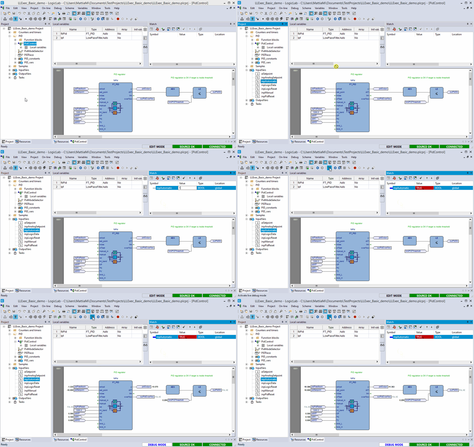
A nice and easy example of FBD editor is the PidControl program (inside the PID folder); this program makes PID regulation using function blocks provided by the libraries included in the project.
Normally the program functionalities are activated by piloting the physical inputs; in this case we will virtually force the inputs values.
The image on the right shows how to manually activate the program; use the watch window to force the value of the global variable inpAutomatic to TRUE (or 1), then activate the live debug mode to get a glimpse of the program behavior.
Double clicking a block instance, if it is not crypted, allows you to quickly enter in the block code editor; in this case, if you double click the FT_PID block you will enter in its source code editor (which is ST).
LD (Ladder Diagram) and IL (Instruction List) editors example
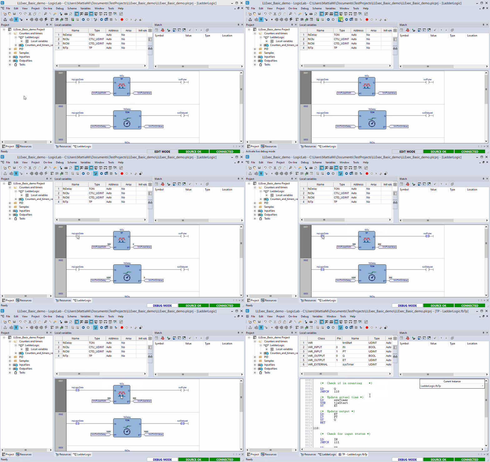
The program LadderLogic, inside the “Counters and timers” folder, is an LD program which implements simple standard counters.
Force the value of inpLogicData to TRUE (or 1) to start the counter (do it using the watch window or double click on the element with the live debug mode active). In fbTp, instance of TP block, you’ll see hmiPulseValue raise until it reaches (or surpasses) the value of hmiPulseWidth.
If you double click on fbTp block, you’ll open it’s souce code editor, which in this case is an IL editor.
In the image on the right the live debug mode is used to force value of inpLogicData; then, after the counter finishes, the sorce code editor of TP block is opened by double clicking the instance.
ST (Structured Text) editor example
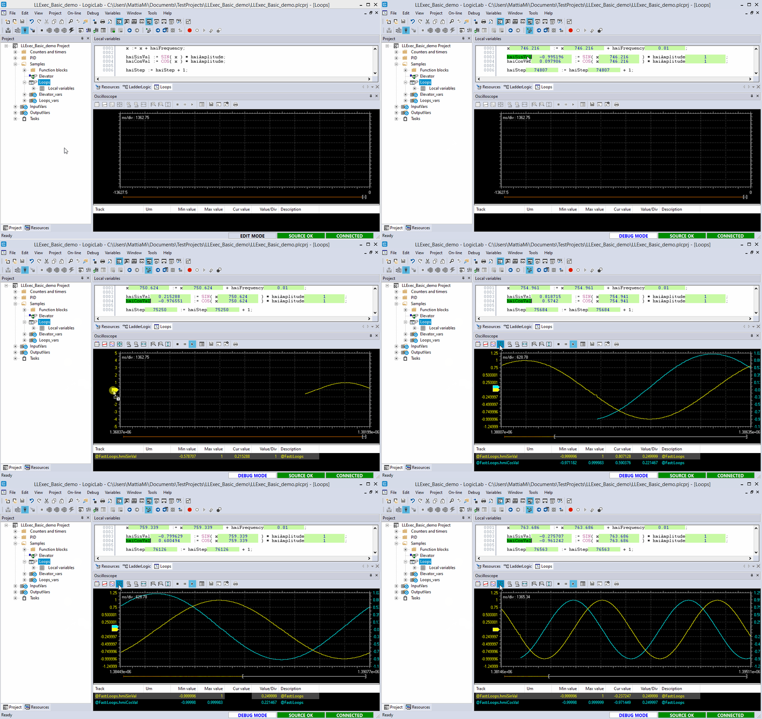
The program Loops, inside the “Samples” folder, it’s an easy ST program which use SIN and COS functions to calculate the sine and cosine of a value.
This program i useful to take a look at how the oscilloscope works.
The image on the right shows the program execution with the live debug mode, then the symbols hmiSinVal and hmiCosVal are added to the oscilloscope and their trace is drawned.
SFC (Sequential Flow Chart) editor example
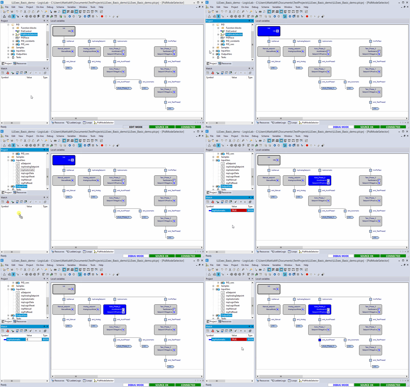
The program PID mode selector, inside the “PID” folder, is a useful program to see how a SFC network is done and how Actions and Transitions are defined and used.
Using the live debug mode here will highlight the blocks under execution, allowing the user to easily identify the path of the chart.
The image on the right shows how the flow changes when the value of inpAutomatic is changed.


